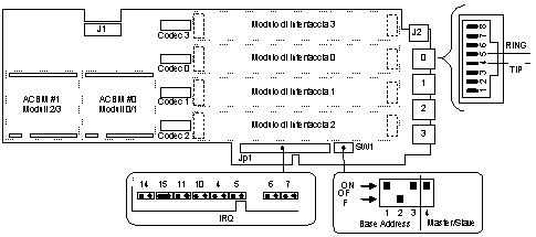

The ACB adapter has the following interfaces and provides the following services:
In each Abilis CPX it is possible to plug in up to 5 ACB adapters in Master/Slave configuration.

Figure 17. ACB adapter.
| Base address | SW1 | Master/Slave selection | SW1 | |||
|---|---|---|---|---|---|---|
| 1 | 2 | 3 | 4 | |||
| 0x320 | ON | off | ON | Master | ON | |
| 0x340 | off | ON | ON | Slave | off | |
| 0x2A0 | ON | ON | off | |||
The JP1 jumpers block select the IRQ level used by the adapter.
The connector J1 is used to connect the ACB master to the ACB slave, configured for the same address.
The connector J2 is used only if at least one FXS interface is plugged: it supplies the requested power to the telephone connected.
![]() CAUTION
CAUTION
When the connector J2 is used, 48V DC and 80V AC are present on the pins; so that before
opening the Abilis CPX always disconnect the electric current plugs.
For correct jumpers/switches configuration, it also depends on the software one, refer to the chapter Ports numbering and adapters configuration.
Each port can be equipped with the chosen interface module, the following figure shows the FXS and FXO modules.
Base configuration of the ACB adapter provides the ports 0 and 1. For being able to use also ports 2 and 3 the following components must be added:

Figure 18. ACB, modules FXS, FXO, ACBM.